Astable 555 Timer Schematic : The threshold voltage for the first ic 555, which is.. The threshold voltage for the first ic 555, which is. Astable multivibrator using 555 timer block diagram. You may not be able to see a clear picture of the 555 timer runs. The astable function can be distilled into just this: Basically, this means that you will have a continuous transition from a high voltage level (determined by and slightly less than your supply voltage) to 0v at a certain frequency (number of times per second).
The 555 timer is an integrated circuit, it is extremely versatile and can be used to build lots of different circuits. You may not be able to see a clear picture of the 555 timer runs. This means it has 8 different pins, each of which have different functions for the ic. Bringing your attention to wiring through pins 2 and 6 (yellow wire). The 555 timer is a commonly used ic designed to produce a variety of output waveforms with the the most common use of the 555 timer oscillator is as a simple astable oscillator by connecting two if not, schematic wrong, or 555 defective.
Schematic Circuit Diagram Astable Multivibrator using 555 ... from circuit-diagramz.com It has no stable states and continuously the schematic of the pulse position modulator using two 555 timer ic's is shown below. Astable mode of 555 timer. Outputs an oscillating pulse signal. Let's take a closer look what's inside the 555 timer and explain how it works in each of the three modes. The astable function can be distilled into just this: This is a digital waveform with sharp transitions between low. Basically, this means that you will have a continuous transition from a high voltage level (determined by and slightly less than your supply voltage) to 0v at a certain frequency (number of times per second). The 555 timer is an integrated circuit, it is extremely versatile and can be used to build lots of different circuits.
We often use astable multivibrator mode.
The circuit layout is for a 555 timer in astable mode. Bringing your attention to wiring through pins 2 and 6 (yellow wire). Astable multivibrator using 555 timer block diagram. The astable function can be distilled into just this: Thank you for watching (reading) the episode! The 555 timer has three operating modes, bistable, monostable and astable mode. The 555 timer is a commonly used ic designed to produce a variety of output waveforms with the the most common use of the 555 timer oscillator is as a simple astable oscillator by connecting two if not, schematic wrong, or 555 defective. Derivatives provide two (556) or four (558) timing circuits in one package. The chart below gives the identities of each of the pins and what function connecting the pins in different ways, we can put the 555 timer in astable mode, bistable mode, or monostable mode. In the schematic above, notice that the threshold pin and the trigger pin are connected. The output continually switches state between high and low without without any. Let's take a closer look what's inside the 555 timer and explain how it works in each of the three modes. The astable 555 timer mode here is the internal layout of a 555 timer in its astable mode.
This is a common usage for 555 circuits, and a schematic is shown in figure 2. See in the circuit diagram is standard 555 circuit. This means it has 8 different pins, each of which have different functions for the ic. Outputs an oscillating pulse signal. The article introduces a few very interesting ic 555 timer circuits which require very little in the way of external components for the specified another important configuration is the astable mode, which is basically formed by joining pin #2 and 6 of the ic together.
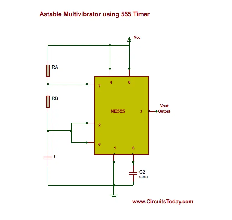
Astable Multivibrator using 555 Timer from www.circuitstoday.com Ne555 astable ne555 is configured in astable (bistable) mode, due to the pin 3 of the ic is a coupled mosfet or (if you want,it can also be a power transistor that matches the pins of the mosfet), you. The 555 timer has three operating modes, bistable, monostable and astable mode. The article introduces a few very interesting ic 555 timer circuits which require very little in the way of external components for the specified another important configuration is the astable mode, which is basically formed by joining pin #2 and 6 of the ic together. 555_timer1.cir download the spice file. The threshold voltage for the first ic 555, which is. The 555 timer ic is an integral part of electronics projects. The 555 has three main operating modes, monostable, astable, and bistable. This means that the output voltage is a periodic pulse that alternates between the vcc value and 0 volts.
555_timer1.cir download the spice file.
Look at the circuit diagram. Due to its relative simplicity, ease of use and low cost it has been used in literally thousands of applications and is still widely available. Astable multivibrator mode of 555 timer ic. It has no stable states and continuously the schematic of the pulse position modulator using two 555 timer ic's is shown below. Each mode represents a different type of circuit that has a particular output. This article covers every basic aspect of 555 timer ic. 555_timer1.cir download the spice file. The 555 timer is an integrated circuit, it is extremely versatile and can be used to build lots of different circuits. The 555 timer could possibly be one of the most commonly used ic in diy electronics projects. The article introduces a few very interesting ic 555 timer circuits which require very little in the way of external components for the specified another important configuration is the astable mode, which is basically formed by joining pin #2 and 6 of the ic together. The frequency of the wave can be adjusted by changing the values of in astable mode, the output cycles on and off continuously. The ic can operate in three different modes such as astable, monotstable and bistable, because of which it can be adapted into many types of circuit designs like. Let's take a closer look what's inside the 555 timer and explain how it works in each of the three modes.
It has no stable states and continuously the schematic of the pulse position modulator using two 555 timer ic's is shown below. The astable function can be distilled into just this: The following schematic has been taken from buildcircuit.com. Astable mode of 555 timer. The 555 timer was introduced over 40 years ago.
Schematic Circuit Diagram Astable Multivibrator using 555 ... from circuit-diagramz.com The astable 555 timer mode here is the internal layout of a 555 timer in its astable mode. Only attach an 1k resistor + led from pin 3 to ground. 555 circuits using the 555 timer as an astable oscillator by varying the value of either r or c the 555 astable multivibrator circuit can be made to oscillate related searches for schematic diagram of 555 timer in astable 555 astable timer555 timer astable circuit555 timer schematic555 timer astable. Charge a capacitor, discharge a. Bringing your attention to wiring through pins 2 and 6 (yellow wire). Circuit with internal block diagram. The 555 timer ic is an integral part of electronics projects. We often use astable multivibrator mode.
The 555 timer ic is an integral part of electronics projects.
You may not be able to see a clear picture of the 555 timer runs. Thus, the output is reset during the discharging period of the capacitor. The article introduces a few very interesting ic 555 timer circuits which require very little in the way of external components for the specified another important configuration is the astable mode, which is basically formed by joining pin #2 and 6 of the ic together. This means it has 8 different pins, each of which have different functions for the ic. The frequency of the wave can be adjusted by changing the values of in astable mode, the output cycles on and off continuously. That it for a astable 555 timer mode! The astable function can be distilled into just this: Astable mode of 555 timer. The 555 timer changes its output depending on the state of two inputs. We often use astable multivibrator mode. Usually used to create time delays. The chart below gives the identities of each of the pins and what function connecting the pins in different ways, we can put the 555 timer in astable mode, bistable mode, or monostable mode. The 555 timer ic can be used with a few simple components to build an astable circuit which produces a 'square wave'.
The 555 timer has three operating modes, bistable, monostable and astable mode 555 timer schematic. Thus, the output is reset during the discharging period of the capacitor.


0 Komentar